
Wire Size Calculator
Size the right electrical wire or cable for any circuit. Enter your load current and get the AWG wire gauge or mm² size for ampacity and voltage drop, matched to your material and code.
How to Use the Wire Size Calculator
- Pick your wiring standard. It sets the code and the units: the National Electrical Code (NFPA 70) sizes in AWG for the US and Canada, International Standard IEC 60364-5-52 sizes in mm² across most of the world, British Standard BS 7671 covers the UK, and Australian/New Zealand Standard AS/NZS 3008.1.1 covers typical Australian conditions; New Zealand has its own part, AS/NZS 3008.1.2.
- Enter the load current in amps. For a known circuit, use its rated amperage or one of the Common circuits presets at the top of the form.
- Set the conductor material, load duration, and wire temperature rating. When in doubt, 75°C fits most modern equipment.
- Sizing a home's main service or feeder? Switch the circuit type to the dwelling option so the NEC 310.12 allowance applies.
- Add the run length, ambient temperature, or bundled conductor count under Adjust for your install when they apply.
- Read the result. You get the conductor size, its ampacity, the breaker, and the ground wire, plus which limit governed the choice.
Wire Size by Amperage Chart (NEC 310.16, 75°C)
A 40 A circuit takes 8 AWG copper. A 60 A circuit takes 6 AWG, and a 100 A feeder takes 3 AWG. The chart below covers every common breaker size, with copper and aluminum read from the 75°C column of NEC Table 310.16. Working from a known gauge instead? The wire gauge chart lists ampacity, mm², and diameter for every AWG size.
One quirk before you read it. The 14, 12, and 10 AWG rows are capped at 15, 20, and 30 A regardless of their raw ampacity, under the small-conductor rule in NEC 240.4(D).
| Breaker / load (A) | Copper (75°C) | Aluminum (75°C) |
|---|---|---|
| 15 A | 14 AWG | 12 AWG |
| 20 A | 12 AWG | 10 AWG |
| 30 A | 10 AWG | 8 AWG |
| 40 A | 8 AWG | 8 AWG |
| 50 A | 8 AWG | 6 AWG |
| 60 A | 6 AWG | 4 AWG |
| 70 A | 4 AWG | 3 AWG |
| 80 A | 4 AWG | 2 AWG |
| 90 A | 3 AWG | 2 AWG |
| 100 A | 3 AWG | 1 AWG |
| 110 A | 2 AWG | 1/0 AWG |
| 125 A | 1 AWG | 2/0 AWG |
| 150 A | 1/0 AWG | 3/0 AWG |
| 175 A | 2/0 AWG | 4/0 AWG |
| 200 A | 3/0 AWG | 250 kcmil |
These are branch-circuit and feeder sizes. A home's main service can run on a smaller conductor under a special allowance, covered in the next section.
Wire Size by Application: Common Circuits
Most homes repeat the same dozen circuits, so their sizes are worth memorizing. A dryer runs 10 AWG copper on a 30 A breaker. A range takes 8 or 6 AWG at 40 to 50 A, and a 48 A Level 2 EV charger needs 6 AWG copper on a 60 A breaker.
Service conductors are the one exception to the chart above. A one-family dwelling, or an individual dwelling unit of a two-family or multifamily dwelling, may size its main service and main power feeder at 83% of the rating on a single-phase 120/240 V system rated 100 A through 400 A, which is why a 200 A service runs on 2/0 copper or 4/0 aluminum rather than the larger feeder sizes. The allowance comes from NEC 310.12.
| Circuit or equipment | Breaker | Copper | Aluminum | Basis |
|---|---|---|---|---|
| Lighting / receptacle | 15 A | 14 AWG | 12 AWG | 240.4(D) |
| Kitchen / receptacle | 20 A | 12 AWG | 10 AWG | 240.4(D) |
| Electric dryer | 30 A | 10 AWG | 8 AWG | 310.16 |
| Electric range / oven | 40 to 50 A | 8 or 6 AWG | 6 or 4 AWG | 310.16 |
| Electric water heater | 30 A | 10 AWG | 8 AWG | 422.13 |
| Central A/C or heat pump | per nameplate | 10 AWG | 8 AWG | 440 (MCA) |
| Level 2 EV charger (48 A) | 60 A | 6 AWG | 4 AWG | 625.41, 125% |
| 100 A sub-panel feeder | 100 A | 3 AWG | 1 AWG | 310.16 |
| 100 A dwelling service | 100 A | 4 AWG | 2 AWG | 310.12 |
| 200 A dwelling service | 200 A | 2/0 AWG | 4/0 AWG | 310.12 |
| 400 A dwelling service | 400 A | 400 kcmil | 600 kcmil | 310.12 |
Two rows deserve a note. A fixed storage-type water heater (120 gal or less) counts as a continuous load, so a 4500 W, 240 V unit sizes at 125% to 10 AWG on a 30 A breaker (NEC 422.13). Air conditioners and heat pumps skip the general math entirely; size them from the minimum circuit ampacity printed on the nameplate, which a typical residential unit meets with 10 AWG (NEC 440).
For a sub-panel feeder, keep the circuit type on branch or feeder. The 83% dwelling allowance only applies to conductors that carry the entire house load.
How to Calculate Wire Size
Wire sizing comes down to two checks, and the larger answer wins. First, the wire has to carry its current without overheating. That limit is called ampacity, and NEC Table 310.16 sets it. Second, the run cannot lose too much voltage along the way. Most online tools only run the second check; feed one of them 200 A at 10 feet and it suggests 18 AWG, a conductor rated for about 14 A.
The breaker comes out of the same math. The overcurrent device is sized to the design current, the load taken at 125% when it is continuous and rounded up to a standard rating in NEC 240.6, and the conductor is then chosen so that breaker can protect it. In practice, ampacity decides short runs and voltage drop decides long ones; everything else is an adjustment to one of those two numbers.
The Two Wire Sizing Formulas
The ampacity check keeps the conductor cool. Its allowable ampacity, after any correction for heat or bundling, has to meet the load. Loads that run three hours or longer count as continuous and are sized at 125% (NEC 210.19(A) and 210.20(A)).
- A = minimum allowable ampacity the conductor must have (amps)
- I = load current, the amps the circuit carries (amps)
- k = 1.25 for a continuous load, 1 otherwise
- Fa = ambient temperature correction factor (NEC 310.15(B)(1))
- Fb = adjustment factor for more than three conductors (NEC 310.15(C)(1))
Example: a 40 A continuous load needs a conductor good for 40 × 1.25 = 50 A, which is 8 AWG copper at 75°C.
Voltage drop protects performance rather than safety. Resistance builds with distance, so a long run delivers less voltage than the panel supplies, and the fix is a larger conductor. The NEC suggests holding branch-circuit drop to about 3%. For hand calculations, the mil-foot form is quickest:
- Vd = voltage drop along the run (volts)
- K = 12.9 for copper, 21.2 for aluminum (Ω·cmil/ft at 75°C)
- I = load current (amps)
- L = one-way circuit length (feet)
- cmil = conductor area in circular mils
Three-phase uses √3 in place of the 2: Vd = (√3 × K × I × L) ÷ cmil.
Whichever check calls for the bigger conductor decides the size. If you only know the load in watts, the watts to amps calculator converts a nameplate rating into the current to enter here, and the kw to amps calculator does the same for a motor or feeder rated in kilowatts.
Wire Temperature Rating and Terminations (NEC 110.14(C))
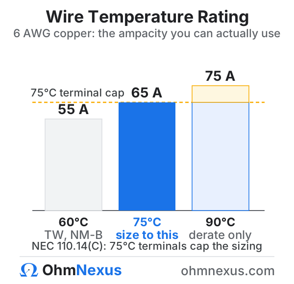
Table 310.16 lists three ampacity columns, rated 60°C, 75°C, and 90°C. The wire's insulation says which columns it can survive. The terminations say which one you are allowed to use.
That second rule surprises people. A 90°C THHN conductor sounds like it should earn the 90°C ampacity, but the breaker and lugs it lands on are almost always listed for 75°C, so the circuit is sized from the 75°C column. Under NEC 110.14(C), equipment rated 100 A or less defaults to the 60°C column unless it is marked for 75°C, and equipment over 100 A uses the 75°C column.
So what is the 90°C column for? Derating math, and nothing else. Start there when correcting for a hot attic or a crowded conduit, then compare the result against the termination column and take the lower number. A 6 AWG copper conductor reads 75 A at 90°C, but on a 75°C breaker its usable ceiling is 65 A no matter what the derating math returns.
Sheathed cable is the common trap here. NM-B (Romex) is built with 90°C conductors, yet NEC 334.80 pins it to the 60°C column, so 8 AWG NM-B is a 40 A cable, full stop.
Continuous Loads, Ambient Heat, and Bundling
Three field conditions can push a wire size past the table value, and they stack.
Continuous loads come first. Anything expected to run three hours or more is sized at 125% of its current, which is why a 32 A EV charger belongs on a 40 A breaker with 8 AWG copper (NEC 210.19(A)).
Heat works differently. The ampacity tables assume 30°C (86°F) ambient air, so a conductor in a 46°C attic is corrected downward before it is compared with the load. The factors come from NEC 310.15(B)(1).
Then there is bundling. More than three current-carrying conductors in one raceway heat each other; four to six drop to 80% of ampacity, seven to nine to 70% (NEC 310.15(C)(1)).
All three corrections multiply against the 90°C column, and the result still has to clear both the load and the termination cap. Skipping them is the classic way a circuit that looks fine on paper runs hot inside a wall. Enter the ambient temperature and conductor count under Adjust for your install and the corrections are already in the number you get back.
Wire Size, Distance, and Voltage Drop
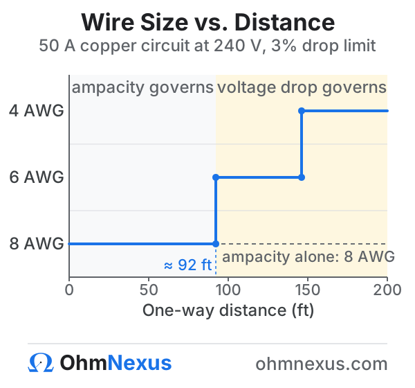
Distance only changes the answer once voltage drop overtakes ampacity, and where that crossover falls depends on the load. A 50 A circuit at 240 V rides comfortably on 8 AWG over short runs. Stretch it to 150 feet and the drop passes 3%, so the conductor steps up to 6 and then 4 AWG.
The 3% figure deserves context. NEC 210.19 and 215.2(A)(2) offer it as an informational note rather than an enforceable rule, with 5% suggested for feeder plus branch combined; a few installations, fire pumps and sensitive electronic equipment among them, do carry hard limits. It is still the right design target. Most engineers stay under it anyway, because one extra wire size costs far less than chasing dim lights, sluggish motors, or nuisance resets after handover.
Two side effects follow from upsizing for distance. The equipment ground has to grow in proportion to the phase conductors (NEC 250.122(B)). And when distance drives the size, the result names voltage drop as the governing limit, so you can see why the wire is larger than the amperage chart alone would suggest.
Voltage itself changes nothing about ampacity. A 100 A feeder is 3 AWG copper whether it runs at 240 V single-phase or 480 V three-phase; the higher commercial voltage only shrinks the drop percentage over the same distance.
Copper vs Aluminum Wire Size
The sizing rule is simple: figure on aluminum running about two AWG sizes larger than copper for the same load. A 100 A copper feeder is 3 AWG; in aluminum it is 1 AWG.
Aluminum shows up on purpose in service entrances and large feeders, and on cost it is hard to beat. Once conductors reach feeder sizes, the copper cost gap gets substantial, which is why utility drops and 200 A services are so often aluminum while branch circuits stay copper.
| Aspect | Copper | Aluminum |
|---|---|---|
| Ampacity per size | Higher | About two sizes lower |
| Typical use | Branch circuits, small feeders | Service entrances, large feeders |
| Terminations | Any listed terminal | Must be CU-AL or AL rated, with anti-oxidant |
| Relative cost | Higher | Lower |
Terminations are where aluminum earned its reputation. The metal expands more with heat and its surface oxide insulates, so a joint on a copper-only lug loosens and overheats over the years. Use terminals listed CU-AL or AL, apply an anti-oxidant compound, and torque to spec, and aluminum is as dependable as anything else in the panel. Size it from the aluminum column, never by taking the copper size and swapping the metal.
Ground Wire Size (NEC 250.122)
The ground wire follows the breaker, not the phase conductor. A 20 A circuit takes a 12 AWG copper ground, a 60 A circuit takes 10 AWG, and a 200 A circuit takes 6 AWG, all from NEC Table 250.122. The result pairs the ground with the conductor and breaker, so the whole circuit is specified in one pass.
| Breaker / OCPD | Copper ground | Aluminum ground |
|---|---|---|
| 15 A | 14 AWG | 12 AWG |
| 20 A | 12 AWG | 10 AWG |
| 30 to 60 A | 10 AWG | 8 AWG |
| 100 A | 8 AWG | 6 AWG |
| 200 A | 6 AWG | 4 AWG |
| 400 A | 3 AWG | 1 AWG |
One distinction saves real confusion. This equipment grounding conductor is the fault-return path back to the panel. The grounding electrode conductor that ties the service to its ground rods is a different animal, sized from NEC 250.66 instead. The two answer different questions and take different sizes.
Wire Sizing Standards: NEC, IEC, BS 7671, and AS/NZS
Pick your wiring standard and the sizing basis follows. North America calls this wire sizing; most of the rest of the world calls it cable sizing and gives a power cable or electrical cable its size in mm² rather than AWG, but the underlying job is the same. The US and Canada share the AWG system and closely aligned ampacity tables, so both size from NEC Table 310.16, with Canadian work confirmed against the CEC (CSA C22.1).
Most other countries size cable in mm² under IEC 60364-5-52, the international standard that national codes adopt with little change: Japan’s JIS, India’s IS 732, South Africa’s SANS 10142, and China’s GB rules all follow it, so the IEC setting covers them. The UK’s BS 7671 builds on the same tables but keeps its own voltage-drop limits (3% lighting, 5% power), which is why it has its own setting here.
- Ib = design current, the load the circuit has to carry (amps)
- In = protective device rating, the next standard MCB at or above Ib (amps)
- Iz = cable current-carrying capacity from the code table, after any derating (amps)
Example: a 20 A design current takes a 20 A MCB, so the cable has to be rated for at least 20 A. Method B PVC copper meets that at 2.5 mm² (Iz = 24 A).
Installation method matters more under IEC than under the NEC, because ampacity swings with how the cable is run. Method B covers cable in conduit in a wall and is the safe default when the method is unknown. Method C is cable clipped to a surface, and Method A is conduit buried in insulation.
BS 7671 reproduces the IEC tables in its Appendix 4, so UK answers match the IEC results. The regs hold voltage drop to 3% for lighting and 5% for other circuits, measured from the origin of the installation, and the drop itself works from conductor resistance:
- Vd = voltage drop along the run (volts)
- Ib = design current (amps)
- L = one-way run length (meters)
- R = conductor resistance in ohms per kilometer (×1.64 for aluminum)
Example: a 20 A load on a 30 m run stays on 2.5 mm² copper for current. At about 7.4 Ω/km the drop is (2 × 20 × 30 × 7.4) ÷ 1000 = 8.9 V, near 3.9% of 230 V. That clears IEC 60364’s 4% guide but tops BS 7671’s 3% lighting limit, so a BS 7671 lighting circuit steps up to 4 mm² (about 2.4%). Three-phase uses √3 in place of the 2, and BS 7671 Appendix 4 gives this same drop as a tabulated mV/A/m per cable.
Australia and New Zealand size cable to AS/NZS 3008.1.1, and its tables are not interchangeable with IEC. The Australian tables (3008.1.1) assume a 40°C air ambient rather than IEC's 30°C, which puts air ratings roughly 12 to 14% lower for the same cable, while the New Zealand part (3008.1.2) is based on 30°C air, and the AS/NZS PVC class is rated 75°C against IEC's 70°C. Voltage drop uses the standard's own tabulated figures, up to the 5% total AS/NZS 3000 allows.
- Vd = voltage drop along the run (volts)
- Vc = tabulated three-phase volt-drop for the cable, in millivolts per amp-meter (mV/A/m, AS/NZS 3008 Table 42)
- I = design current (amps)
- L = one-way route length (meters)
Single-phase multiplies Vc by 1.155. A 20 A single-phase load on 2.5 mm² copper (Vc = 15.6) over 30 m drops (15.6 × 1.155 × 20 × 30) ÷ 1000 = 10.8 V, 4.7% of 230 V, inside the 5% AS/NZS 3000 allows.
The protective earth in AS/NZS 3000 is sized from the active conductor through Table 5.1, the way NEC 250.122 sizes the ground from the breaker. A 16 mm² active takes a 6 mm² earth, a 50 mm² active takes a 16 mm² earth, and a 120 mm² active takes a 35 mm² earth; above roughly 35 mm² the earth settles near half the active size.
All three systems answer the same question in different units. A 32 A circuit lands on 4 mm² copper under IEC Method B, close to the 8 AWG a US electrician would pull. The crosswalk below covers the common sizes; a full gauge conversion belongs on a dedicated AWG chart.
| AWG | mm² (nominal) |
|---|---|
| 14 AWG | 2.1 mm² |
| 12 AWG | 3.3 mm² |
| 10 AWG | 5.3 mm² |
| 8 AWG | 8.4 mm² |
| 6 AWG | 13.3 mm² |
| 4 AWG | 21.2 mm² |
| 2 AWG | 33.6 mm² |
| 1/0 AWG | 53.5 mm² |
New editions of the NEC arrive on a three-year cycle from the National Fire Protection Association, with the 2023 edition (NFPA 70-2023) current; international sizing follows IEC 60364-5-52. State adoption lags publication, so confirm which edition your authority having jurisdiction enforces before finalizing a design.
Common Wire Sizing Mistakes
- Sizing on voltage drop alone. The drop formula says nothing about heat; a conductor that passes 3% can still be far below the ampacity the load needs. Run both checks.
- Terminating to the 90°C column. That column feeds the derating math only; the breaker and lugs cap the final ampacity at 60°C or 75°C (NEC 110.14(C)).
- Forgetting the 125% continuous factor. A 48 A continuous EV load needs a 60 A circuit and 6 AWG copper, not the 8 AWG the raw number suggests.
- Ignoring heat and bundling. A hot ceiling space or a crowded raceway can each knock double-digit percentages off ampacity, sometimes enough to force the next size.
- Reusing a copper size for aluminum. Aluminum runs about two sizes larger for the same load and needs CU-AL rated terminals with anti-oxidant compound.
- Mixing up the two grounds. The circuit's equipment ground follows the breaker (NEC 250.122); the service's grounding electrode conductor follows NEC 250.66.
Disclaimer: This wire size calculator estimates conductor size from NEC Table 310.16 (or IEC 60364-5-52 or AS/NZS 3008) for the values you enter, and its voltage-drop check uses standard resistance constants. Real installations involve conductor temperature, insulation type, raceway material, and local amendments that can change the result. Always verify against the electrical code and the authority having jurisdiction (AHJ) enforced where you work, and consult a licensed electrician or professional engineer for installation and design decisions.
Lighting circuits are a common case: our guide to installing recessed lighting works through circuit load, breaker choice, and the NEC clearances for ceiling fixtures.
Frequently Asked Questions
How do you calculate wire size?
Run two checks and keep the larger answer. The conductor's ampacity from NEC Table 310.16 has to meet the load, at 125% if the load is continuous and after any heat or bundling correction. Then the voltage drop over the run should stay near 3% on a branch circuit. Short runs are decided by ampacity, long runs by voltage drop. A 40 A circuit needs 8 AWG copper before distance even enters the picture.
What size wire do I need for a 50 amp breaker?
8 AWG copper or 6 AWG aluminum, assuming 75°C terminations, which cover most modern equipment. On 60°C terminals, or with NM-B (Romex) cable, step up to 6 AWG copper, because 8 AWG only carries 40 A in the 60°C column. Electric ranges are the common 50 A load and usually run 6 AWG for exactly that reason.
What size wire is needed for a 100 or 200 amp service?
A 100 amp dwelling service uses 4 AWG copper or 2 AWG aluminum, and a 200 amp service uses 2/0 copper or 4/0 aluminum. Both are smaller than a feeder of the same rating because a single-family home may size its main service and main power feeder at 83% of the rating (NEC 310.12). A 100 amp sub-panel feeder gets no such break and stays at 3 AWG copper.
Should I size wire by ampacity or by voltage drop?
Both, then keep whichever gives the larger conductor. Ampacity is the safety floor; the wire has to carry its current without overheating, and NEC 310.16 sets that limit. Voltage drop is a performance target, with the NEC recommending about 3% on a branch circuit. Checking only one of the two is how circuits end up dangerously undersized.
What size ground wire do I need?
Size it from the breaker rating using NEC Table 250.122. A 20 A circuit takes a 12 AWG copper ground, a 30 to 60 A circuit takes 10 AWG, a 100 A circuit takes 8 AWG, and a 200 A circuit takes 6 AWG copper. Upsize the phase conductors for voltage drop and the ground grows in proportion (NEC 250.122(B)).
How does the wire temperature rating change the size?
It picks which column of NEC 310.16 you read, and the terminations cap the choice. Most equipment is listed for 75°C, so circuits are sized from that column even when the wire is 90°C THHN. The 90°C figures exist for the derating math only; landing them directly on a breaker undersizes the wire below what NEC 110.14(C) allows.
Get early access to OhmNexus Pro
Join the list for new calculators, guides and services, plus first access to our upcoming advanced and AI-assisted design tools. No spam; unsubscribe anytime.
Need more electrical tools?
View All Calculators